Follow these steps to connect your FX device to a Dynon SkyView system. Special thanks to Danny at Mendelssohns Pilot Supplies for providing pre-made cables, which can be purchased to simplify this connection. Mendelssohn Pilot Supplies.
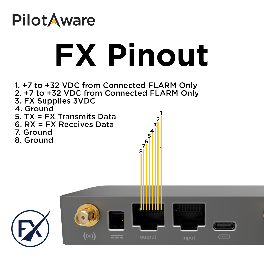
Refer to the FX pinout diagram:
1. Ground Pin: Choose any of the ground pins (4, 7, or 8).
2. Data Transmit Pin: Use pin 5, which transmits the serial data to the Dynon SkyView.

Solder the ground wire from the FX device to any ground pin on the D37 connector block of the Dynon SkyView. Possible options include:
• Pin 17: USB Ground (Black)
• Pin 21: Ground (Black)
• Pin 22: Ground (Black)
• Pin 23: Ground (Black)
• Pin 24: Ground (Black)
Pin options have been taken from the "Skyview System Installation Guide - Revision AQ.
Solder the data transmit wire from the FX device to any spare Serial RX pin on the D37 connector block of the Dynon SkyView. Possible options include:
• Pin 3: Serial Port 1 RX (Brown with Violet stripe)
• Pin 7: Serial Port 3 RX (Green with Violet stripe)
• Pin 9: Serial Port 4 RX (Blue with Violet stripe)
For this example, let’s choose Serial Port 3 RX (Pin 7).
1. Power on the FX device.
2. Connect to the FX device via Wi-Fi and navigate to the FX interface at 192.168.1.1.
3. Go to the Settings page.
4. Under Advanced Settings, set the RS232 protocol to “Automatic”.
5. Select an appropriate baud rate for the Dynon SkyView. The highest rate, 115200, is recommended for maximum data throughput.

1. On the Dynon SkyView display, navigate to its settings.
2. Configure the selected serial input (in this example, Serial Port 3) to receive FLARM traffic.
3. Set the baud rate to match the FX device setting (115200).


1. Ensure the FX device has a GPS lock.
2. Once locked, the FX device will start streaming NMEA data to the Dynon SkyView serial port.
3. Verify that the valid messages are being received on the Dynon SkyView.
4. The traffic data from the FX device should overlay on the Dynon SkyView map.

By following these steps, you will successfully connect your FX device to the Dynon SkyView system, allowing seamless data transmission and traffic overlay on your display.
For additional support or to purchase pre-made cables, please visit Mendelssohns Pilot Supplies.